Load motor induction tests rotor blocked test ppt powerpoint presentation Pin on electrical engineering No load and block rotor test on three phase induction motor
Blocked Rotor Test of Induction Motor - ElectricalWorkbook
No-load & blocked rotor test, equivalent circuit, phasor diagram A "media to get" all datas in electrical science...!!: no load and Blocked rotor test of induction motor
Rotor induction blocked winding phase circuit testing calculation 3p calculate quora electrical4u calculations
Induction rotor slip blocked standstill equivalentWhat is blocked rotor test of induction motor No load and blocked rotor test on single phase induction motorNo load and blocked rotor test.
Blocked rotor test of induction motorNo-load and blocked rotor test No-load & blocked rotor test, equivalent circuit, phasor diagramNo-load & blocked rotor test, equivalent circuit, phasor diagram.

What is blocked rotor test of induction motor
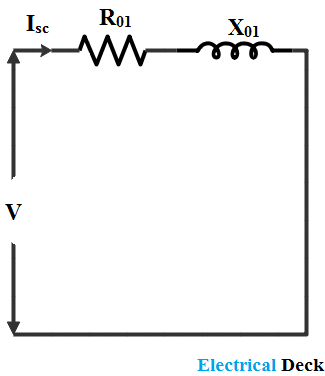
Blocked rotor test of induction motorRotor blocked equivalent phasor locked voltage Rotor test blocked motor induction circuit diagramBlocked-rotor test (theory) : electrical machines laboratory.
Applying short circuit (blocked rotor) test on three-phase inductionBlocked rotor test circuit Test rotor load blockedRotor induction blocked prevented rotating.
Computations and circle diagrams:blocked rotor test
Blocked rotor test of induction motorFigure (a) blocked rotor test of three-phase induction motor Rotor induction blockedBlocked rotor test.
No-load & blocked rotor test, equivalent circuit, phasor diagramNo-load and blocked rotor tests on induction motor Computations and circle diagrams:blocked rotor testTest motor induction load rotor blocked.

No-load & blocked rotor test, equivalent circuit, phasor diagram
Rotor blocked relevantCircuit diagram representation of blocked rotor test conduct of im No-load & blocked rotor test, equivalent circuit, phasor diagramPhasor rotor blocked equivalent.
No load blocked rotor and load test on induction motor(a) schematic diagram of locked rotor test (b) lspmsm q-circuit under No load and blocked rotor test on single phase induction motorWhat is blocked rotor test of an induction motor?.

Rotor projects
Rotor blocked theory electricalTest rotor blocked load induction motor equivalent circuit datas electrical science get phase Rotor locked blockedRotor induction motor test blocked electrical4u.
Solved considering the blocked rotor equivalentCircuit rotor blocked No load test and blocked rotor test-single phase induction motor.


no load and blocked rotor test - YouTube

Figure (a) Blocked rotor test of three-phase induction motor

No-load & blocked rotor test, Equivalent circuit, Phasor diagram

Pin on Electrical Engineering

Blocked Rotor Test of Induction Motor - EEEGUIDE.COM

Blocked Rotor Test of Induction Motor - ElectricalWorkbook

No-Load and Blocked Rotor Test - javatpoint
